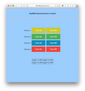
Here’s a really easy demonstration of how you can control outputs on the NodeMCU with a simple web interface. The NodeMCU runs as a simple web server, writing a control panel interface directly as HTML.
Hardware
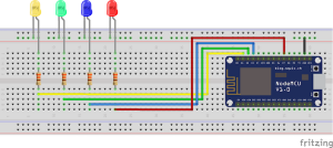
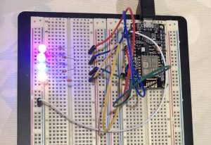
The circuit is very simple, just four LEDs with resistors wired to outputs of the NodeMCU.

Here’s the wiring I used, which matches the code.
- yellow – D1 = GPIO5
- green – D2 = GPIO4
- blue – D3 = GPIO0
- red – D7 = GPIO13
In Arduino code, GPIO numbers map to Arduino digital outputs, so to turn on yellow LED use digitalWrite(5, HIGH)

Software
- Get the code example (esp8266ledControl.ino) and edit to add your wifi name and password to the code.
- Board type in Arduino IDE is ‘Node MCU 1.0 (ESP-12E Module)’
- You will need to set up your Arduino IDE to work with the NodeMCU. A good guide can be found at https://www.circuito.io/blog/nodemcu-esp8266/ (go to the last section Programming NodeMCU with Arduino IDE. Note there is a slight typo in the instructions, the board URL should end with ‘.json’ not ‘.jso’).
- Upload the code to the NodeMCU.
- When it has finished loading, quickly open the Serial Monitor, set the baud rate to 115200.
- Wait until the device joins the WiFi network, and note the IP address it obtains.
- Enter this address in a web browser, and the interface will load.
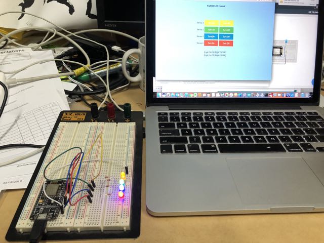
- Now you can turn on and off the various coloured LEDs by clicking on the respective buttons.

