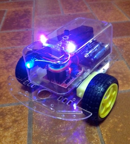
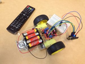
My son entered Science Talent Search with this Arduino-powered buggy. We used IR with a TV remote to issue codes for motor control and combinations of colours for the RGB LEDs.
Programming was fairly simple, but we found issues with power. It seems that motors are very noisy and when they run it can reset the Arduino. We solved this by running the motor off 4 x AA batteries, whilst the Arduino is powered by a phone battery booster. The Arduino in question is actually a Freetronics Leostick, which is a nice small board, and has a USB plug which we just plugged straight into the phone battery.
I bought a NodeMCU module a while back, but couldn’t figure out how to use it at the time. I also played with one of the ESP8266 modules using a FTDI adaptor to also convert to 3V3, but it seemed rather flaky. In the end, I found I could simply hook up the NodeMCU to a USB port and use the Arduino IDE. To save a whole lot of messing around, I also set up Blynk, which works briliantly with this type of device. One slight complication is that the NodeMCU tries to map pins to equivalent Arduino pinouts, whilst Blynk is still aware of the GPIO pinouts. Finding a pinout diagram here helped make sense of it.
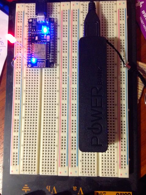
NodeMCU on breadboard, with one LED connected. Note el cheapo phone booster battery doing a great job.
It also seems that the USB ports on my MacBook Pro aren’t reliable with this device, whether it isn’t so happy with USB 3.0 ports or whether it’s not supplying enough current I can’t tell. When it shows up it is easy to flash it with the Arduino sketch. Plugging the board into a phone charger it works 100%. I’m also testing out an el cheapo phone battery booster from K-Mart as a portable power source for projects, and at only $5 this is great value, so I plan to pick up a few more.
Test Blynk project. The red LED is on the breadboard, and the other two are blue LEDs on the NodeMCU board.
Suddenly I see a whole lot of benefits of using these inexpensive NodeMCU boards in place of Arduinos for lightweight projects, considering that you get Wi-Fi built in.
So it’s been busy, and school is just about to go back. I did find time to try out my Christmas present so I opened up the kit, plugged in the SD card and WiPi adaptor, hooked up peripherals that normally are hooked up to the Mac Mini, plugged in the power and we’re up and running. A few clicks and we’ve joined the network and posting a new item on this blog!
So this project had been sitting on my desk for ages now with the sensors and RF module spread across two breadboards with a mess of wire connecting it all up. Today I finally found some time to add the RF module to a prototyping shield. The other sensors are still on a breadboard and that’s the extra wires hanging off it, but it’s one step closer to a finished project. Some of the soldering was a bit fiddly but worked straight off.
Last week just as we were getting used to sunshine again the weather reminded us it’s still winter. Sitting in a meeting Thursday afternoon hearing the wind and rain crashing around the building I pulled up the weather feed and you can see when it really hit.
This shot is from about 4:25pm. Temperature dropped about 10 °C in an hour. You can see the humidity shot up too with the rain.
This morning we woke up to a coating of frost on everything, and the weather station told me that despite the bright sunny morning it was -0.4 °C outside. Guess there’s still more days to go skiing this season!
After merging the XC0348 code I had which was receiving the data transmitted by the outdoor sensors with the Xively code there was a bit of tweaking to do to get the sketch to play nicely. The last step was to add the code back for the pressure sensor. This was problematic as the sensor uses I2C and soon as I added the Wire library the whole thing stopped running properly. After some reading I wondered if I was just running out of memory so I commented out a whole lot of serial print statements and it this got things working again. Of course, without the print statements there was a whole lot less debugging going on.
A couple of things that still need attention:
the pressure sensor has been timing out often, so I get false values where a negative error code is returned. I’ve increased the timing loop and am seeing if this works better
we had a heap of rain overnight and my rainfall figure suddenly dropped because I was only using the LSB, and the count had overflowed. A bit of trial and error and now it is showing the true total. A problem with rainfall is that the sensor reports total rainfall, so this will just keep going up and up. I need some way to keep daily totals. Perhaps I need to add a real time clock?
my light values are related to the resistance in the photoresistors, so the curves are inverted i.e. when it is light the value is lowest FIXED Apr 10 – I chose an arbitrary dark value of 1000 and am using that as a reference point to subtract from, so now a bigger value does mean more light rather than more dark!
wind direction is returned as an integer between 0 and 31, which seem to correspond to 16 compass points. I think there might be some sort of moving average calculation used by the base station to reduce errors due to rapidly fluctuating wind shifts.
This is an Arduino with an OLED display in a tiny package.
This is very cool …
I’m thinking I might have to back this one, which has already reached its target after less than 24 hours. It’s Aussie-designed although being made in the USA. Read more on Kickstarter. Now what could I use it for …
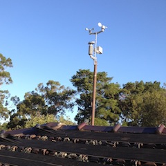
Home early from work and a beautiful afternoon, so I thought, it’s time to install the weather station sensor array on the roof. There is a pipe from a flue or something up there that is doing nothing and ideal. Didn’t take too long, used the compass on the phone and checked the satellite image on Google Maps to get a good idea of where North is. Even whilst I was up there I could see that it was picking up much more wind rather than when it had been down low and sheltered.
There’s a whole heap of updates still to write, but this is now sending data to my Arduino which is getting pushed to the internet along with some data from sensors inside the house.