All posts by foxadmin

Weather station update

Realised this project has been running almost 10 years now, and gone through several iterations. The main improvement is that it is integrated with my Home Assistant system.

Latest version of the weather station receiver.

Note that in the process it has gone back to a breadboard, so far from a finished project yet! The circuit operates as such:

  • RF receiver module running at 433 MHz receives the data pulse from the rooftop sensors
  • Arduino Nano decodes the sensor data into meaningful values
  • Data is converted to JSON and transmitted via serial to ESP8266, using level shifter to allow 5V Arduino output to input to ESP which expects 3.3V levels
  • ESP8266 receives JSON packet and then passes this via MQTT to the Home Assistant over WiFi
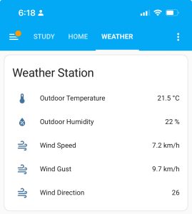
  • Individual sensor data displayed on HA page
Home Assistant data display

As before, because this is intercepting data from outside sensor, it only gives me outside temperature and humidity, wind speed and direction. (Note direction is still an arbitrary number, must figure out how to convert this to meaningful compass direction one day). This is supplemented by separate ESP boards inside the home sending their temperature and humidity data via the ESPHome integration over WiFi.

During the last week it stopped receiving data from the rooftop unit, and I suspected perhaps this time it had finally packed it in after almost a decade of use. The fact that neither the console or my circuit were reporting data would suggest an issue with the transmitter. Previously I have had to replace the Alkaline rechargeable AA cells it uses, which are not the easiest things to find these days. The cockatoos have also had some fun with it also, with only two of three anemometer cups surviving and some of the wires have been chewed but still seem to be working.

So I climbed up on the ladder to get on the roof, pulled down the transmitter to find it is still working fine. Recalled this has happened before, so I pulled batteries from the wall mounted console to restart it and it picked up the transmitter straight away. Which means of course I have to set the date and time again, no memory backup šŸ™

This leaves the question of why my receiver was still not working. Plugging into the Arduino IDE let me check data being received. The ESP was connecting to WiFi, but not receiving from the Arduino, although it was showing data transmission on status lights. On debugging it, found that the transmitter ID code had shifted, which seems to happen from time to time, but I don’t know why. So, what seems to happen is, transmitter ID changes, base station console doesn’t notice and keeps trying to listen to previous ID. Meanwhile, my circuit is hardcoded for the ID. Otherwise it tends to pick up spurious transmissions from other devices, I would expect these could be air conditioner remotes, garage door remotes, etc all of which are using 433MHz RF band.

So restarting the base station made it listen for a new transmitter ID, and I had to update my code for the new ID before it would start reporting the data! I can’t think of an easy way to make this happen automatically, but at least next time I’m going to know what to try before getting up on the roof again.

Macintosh SE reboot

Amongst a collection of ancient computer gear, I have my Mac SE which was my first Mac, following on from the Apple IIe and IIgs. I bought this in about 1987, and it served well for many years, including some tentative steps to becoming a programmer. Originally bought as a twin floppy with 1MB RAM, then updated to 4MB, I had a whopping 67MB Rodime SCSI hard drive installed for an equally whopping price. The third party update put the drive inside whilst leaving both floppy drives installed, unlike the standard Apple configuration which replaced one floppy with the internal drive.

Many years later, the internal drive stopped working meaning it was of limited use, but by then I had moved onto a Mac IIsi. Since then it was stored, with the hard drive removed, and some attempts to replace it with a spare one pulled from another Mac. I also removed one of the floppies which had stopped working at some point.

Fast forward to recent times, and several enterprising individuals have worked out how to build emulators based on microcontrollers using SD cards as storage devices. I obtained a BlueSCSI board. This is the original design, using an STM32 microcontroller, although newer versions also make use of a Raspberry Pi Pico board. It is ironic that the microcontroller boards have more processing power than the Mac they are installed in.

BlueSCSI board
BlueSCSI board (credit: Tom Bl @FB)

The vendor kindly gave me an adaptor header which converts the 50-pin SCSI header into a DB-25 plug so that the board can be plugged straight into the external SCSI port not requiring you to open the case. You copy a disk image for the hard drive to a microSD card, then when the Mac starts up it sees the board as normal HD. Some initial trials established that a) it works well but b) I couldn’t use the System 7 image provided as I had reverted to the original 1MB of RAM.

For software images and articles, a fantastic site is https://www.savagetaylor.com. Here’s a helpful guide, written for a different SCSI emulator board but the software works the same.

Warning: Opening up a compact Mac is not a trivial matter! These were never designed to be user-serviceable and in particular all of the service manuals are very clear on taking precautions to not get blasted by the high voltage charge stored by the CRT. If you don’t know what you are doing, don’t open the case!

Put aside for a few months until the end of the year when I had holiday time to continue. Restored to 4MB of RAM, working well with System 7 disk images. Put aside again whilst I thought about whether I wanted to hide the board inside or just plug into SCSI port. First is better but then you can’t access the SD card to modify software. Second is inconvenient as you have to plug in every time and it gets in the way of the external floppy port too.

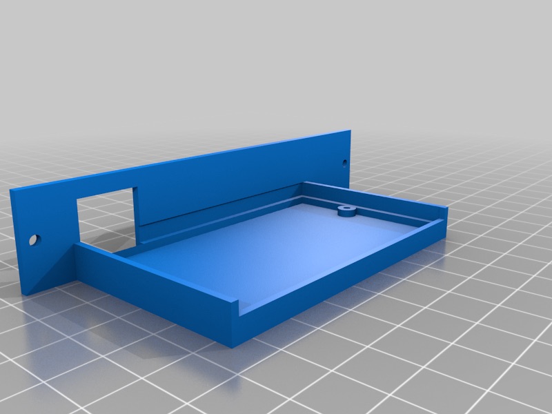
Best solution, I found a 3D print for a tray that lets you install into the PDS slot opening on the back whilst still allowing access to the SD card. Opened up again, and a little bit of adjustment and all good! Back to life!

3D printed tray for BlueSCSI board (credit: https://www.thingiverse.com/thing:5358068)

At present, the only way to change software on the computer is either from old disks or modifying the disk image on the SD card. Obviously there is no internet connection to easily download files! Future steps might be to set up an emulator on my modern Mac so I can move files back and forth.

Been a long time …

Just realised that I haven’t posted here in a long time, started a new role at a new school start of 2022 and that has been keeping me busy … in a good way.

Few projects that have been looked at in this time:

  • I did build a finished version of the RGB light controller on strip board, worked quite nicely
  • Lots of Home Assistant experimentation, including an updated receiver for the weather station to post data to HA via MQTT
  • I fixed our pool chlorinator controller, ended up being a dry solder joint, saved myself about $2000 that it would have cost to replace it
  • Brought the Macintosh SE back to life with a BlueSCSI card, this basically replaces a failed SCSI hard drive with a microcontroller and a microSD card (go read the post here).

Almost end of school holidays, which is usually when I have some time to reflect, perhaps there will be another detailed post for one of these projects?

RGB Light CONTROLLER

I scored some of these analog RGB strips and needed a way to power them, and to be able to control the colours.

Initial prototyping showed that I needed about 20V to be useful, and I could easily switch each colour via a MOSFET driven from a microcontroller. First attempt was with an Arduino, then another with an ESP8266. At this point, I realised that you have to choose the MOSFET gate voltage to suit the logic, so common IRF540 devices won’t work with the 3.3 V available to ESP devices. I selected IRLB8271 instead, and this works.

I have tried a few different circuits, involving different coding.

  • Cycling through colours
  • Random colour cycle
  • Running a web server, using a web page to choose colours

Now to get from the breadboard to a finished circuit …

Useful links

555 Project part 2

From design to PCB

This year with students back in the classroom it was time to resume the development process. I was able to use a professional development day in Term 2 to finally get to grips with KiCad. I had already looked at a tutorial so using that as a reference I started the process to turn this circuit into a finished PCB that I could use in classes.

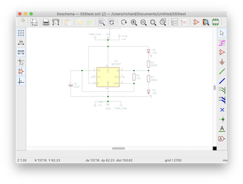
Eeschema editor

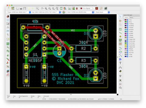
Following the steps in the KiCad tutorial I was able to create the circuit, then export this to a board design, choosing the appropriate footprints for components. Next step was to do the layout and connect up the tracks.

Finished PCB layout in KiCad

KiCad has a very neat 3D viewer which means you can view a finished board before it even gets produced.

The 3D viewer even populates the board with components

Previously I had ordered some PCBs from others’ designs from PCBWay as a test. From KiCad I was able to export my board layers as Gerber files. PCBWay has a quick feature where you just upload the Gerber files and it does all of the configuration. Their prototype rate means that you can get 10 boards made for just USD$5, but unfortunately the shipping costs rather more. Nevertheless, the service is incredibly quick, from submitting the order on Wednesday to receiving it on Monday morning, from China to Australia. The unit cost will come down when I order larger numbers for production.

10 + 1 for free!

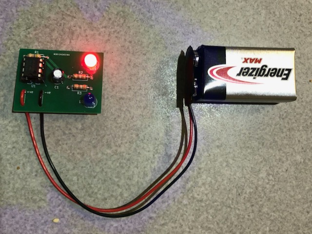
When the boards arrived, 5 minutes work with the soldering iron and a finished product.

Success!

555 project part 1

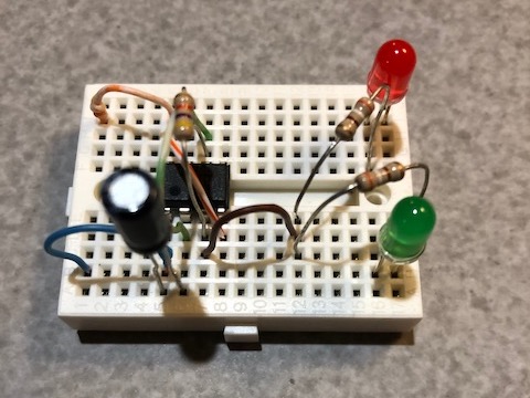
Two years ago I had my students prototyping a simple 555 based LED flasher circuit on breadboards.

Prototype on mini breadboard

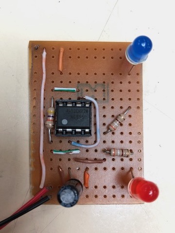
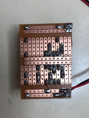
The next step involved transferring this to strip board so they could make a permanent circuit to take home. This part of the process proved troublesome as Veroboard is difficult to work with due to the close spacing of tracks, and the inability of students to follow placement instructions precisely.

In 2020 we started the year, but then COVID-19 intervened and students did not attend school, so did not build physical projects or do soldering.

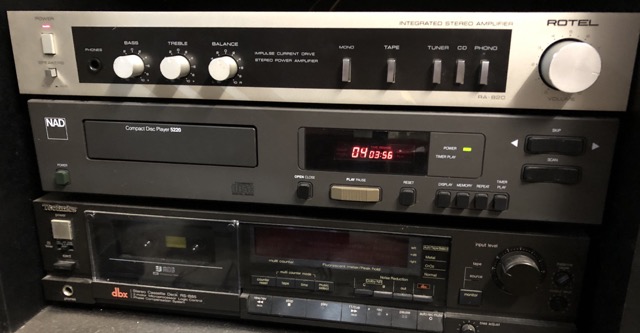
Rotel amp restored

Picked up a couple of dead hi-fi amps, one of them being this nice Rotel RA-820. Opened it up, gave it a clean and replaced all the electrolytics and back in business. Now sitting in the garage hi-fi cabinet for when I’m working down there.

Useful links:

The other amp is a Cambridge Audio A-300 (like this A-500) but it looks to be in rather a sorry state, with at least one blown output stage. Have to work out whether that one is going to be worth restoring, or may get rebuilt as a chip amp …

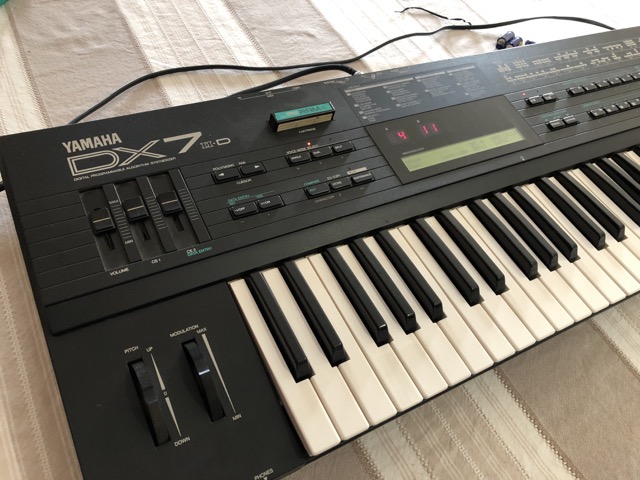
DX7 IID resurrected

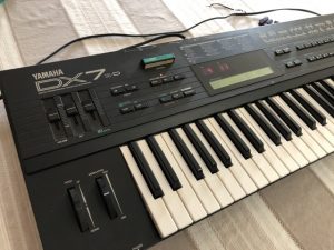
This clever piece of tech was behind much of the pop music of the 80s. I picked one up second hand sometime later, and had some fun with it. I got it out of the cupboard last year to fire it up, but sadly it wasn’t working. Nothing. Nada. Not a sausage. I opened it up, did some quick checks and established that the power supply seemed to be problem. Because these things were produced in the hundreds of thousands, there is plenty of information around. I found service manuals that show part layouts and circuit diagrams. A forum suggested that it was likely to be the electrolytic capacitors that would fail in the power supply.

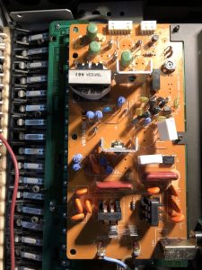
power supply board, caps removed

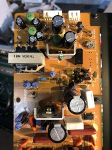
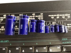
I desoldered the old capacitors, and several of them tested as a short circuit. I ordered the required values online, and had them a week ago, but finally had time today to replace them. Very pleased to find that the synth powers up, and all of the presets are still saved as well. 9 capacitors worth about $10 and it is back in action.

power supply board, new capacitors added

the old electrolytics that were replaced

good for another 30 years

NodeMCU electronic switch

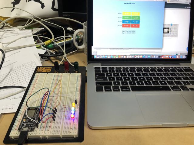
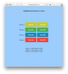
Here’s a really easy demonstration of how you can control outputs on the NodeMCU with a simple web interface. The NodeMCU runs as a simple web server, writing a control panel interface directly as HTML.

Hardware

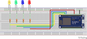
The circuit is very simple, just four LEDs with resistors wired to outputs of the NodeMCU.

wiring diagram
wiring diagram

Here’s the wiring I used, which matches the code.

  • yellow – D1 = GPIO5
  • green – D2 = GPIO4
  • blue – D3 = GPIO0
  • red – D7 = GPIO13

In Arduino code, GPIO numbers map to Arduino digital outputs, so to turn on yellow LED use digitalWrite(5, HIGH)

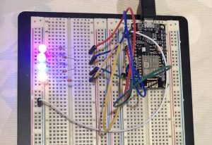
NodeMCU circuit
NodeMCU circuit

Software

  1. Get the code example (esp8266ledControl.ino) andĀ edit to add your wifi name and password to the code.
  2. Board type in Arduino IDE is ‘Node MCU 1.0 (ESP-12E Module)’
  3. You will need to set up your Arduino IDE to work with the NodeMCU. A good guide can be found atĀ https://www.circuito.io/blog/nodemcu-esp8266/ (go to the last section Programming NodeMCU with Arduino IDE. Note there is a slight typo in the instructions, the board URL should end with ‘.json’ not ‘.jso’).
  4. Upload the code to the NodeMCU.
  5. When it has finished loading, quickly open the Serial Monitor, set the baud rate to 115200.
  6. Wait until the device joins the WiFi network, and note the IP address it obtains.
  7. Enter this address in a web browser, and the interface will load.
  8. Now you can turn on and off the various coloured LEDs by clicking on the respective buttons.

web interface
web interface