Category Archives: Arduino

Weather station update

Realised this project has been running almost 10 years now, and gone through several iterations. The main improvement is that it is integrated with my Home Assistant system.

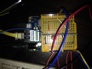
Latest version of the weather station receiver.

Note that in the process it has gone back to a breadboard, so far from a finished project yet! The circuit operates as such:

  • RF receiver module running at 433 MHz receives the data pulse from the rooftop sensors
  • Arduino Nano decodes the sensor data into meaningful values
  • Data is converted to JSON and transmitted via serial to ESP8266, using level shifter to allow 5V Arduino output to input to ESP which expects 3.3V levels
  • ESP8266 receives JSON packet and then passes this via MQTT to the Home Assistant over WiFi
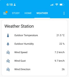
  • Individual sensor data displayed on HA page
Home Assistant data display

As before, because this is intercepting data from outside sensor, it only gives me outside temperature and humidity, wind speed and direction. (Note direction is still an arbitrary number, must figure out how to convert this to meaningful compass direction one day). This is supplemented by separate ESP boards inside the home sending their temperature and humidity data via the ESPHome integration over WiFi.

During the last week it stopped receiving data from the rooftop unit, and I suspected perhaps this time it had finally packed it in after almost a decade of use. The fact that neither the console or my circuit were reporting data would suggest an issue with the transmitter. Previously I have had to replace the Alkaline rechargeable AA cells it uses, which are not the easiest things to find these days. The cockatoos have also had some fun with it also, with only two of three anemometer cups surviving and some of the wires have been chewed but still seem to be working.

So I climbed up on the ladder to get on the roof, pulled down the transmitter to find it is still working fine. Recalled this has happened before, so I pulled batteries from the wall mounted console to restart it and it picked up the transmitter straight away. Which means of course I have to set the date and time again, no memory backup šŸ™

This leaves the question of why my receiver was still not working. Plugging into the Arduino IDE let me check data being received. The ESP was connecting to WiFi, but not receiving from the Arduino, although it was showing data transmission on status lights. On debugging it, found that the transmitter ID code had shifted, which seems to happen from time to time, but I don’t know why. So, what seems to happen is, transmitter ID changes, base station console doesn’t notice and keeps trying to listen to previous ID. Meanwhile, my circuit is hardcoded for the ID. Otherwise it tends to pick up spurious transmissions from other devices, I would expect these could be air conditioner remotes, garage door remotes, etc all of which are using 433MHz RF band.

So restarting the base station made it listen for a new transmitter ID, and I had to update my code for the new ID before it would start reporting the data! I can’t think of an easy way to make this happen automatically, but at least next time I’m going to know what to try before getting up on the roof again.

NodeMCU electronic switch

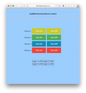
Here’s a really easy demonstration of how you can control outputs on the NodeMCU with a simple web interface. The NodeMCU runs as a simple web server, writing a control panel interface directly as HTML.

Hardware

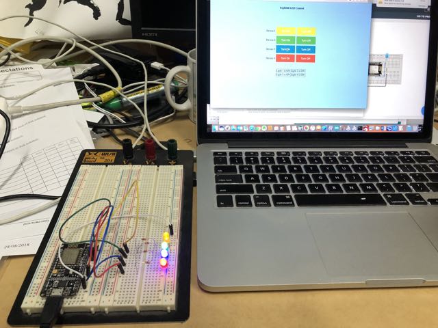
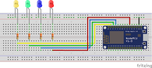
The circuit is very simple, just four LEDs with resistors wired to outputs of the NodeMCU.

wiring diagram
wiring diagram

Here’s the wiring I used, which matches the code.

  • yellow – D1 = GPIO5
  • green – D2 = GPIO4
  • blue – D3 = GPIO0
  • red – D7 = GPIO13

In Arduino code, GPIO numbers map to Arduino digital outputs, so to turn on yellow LED use digitalWrite(5, HIGH)

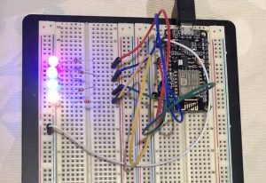
NodeMCU circuit
NodeMCU circuit

Software

  1. Get the code example (esp8266ledControl.ino) andĀ edit to add your wifi name and password to the code.
  2. Board type in Arduino IDE is ‘Node MCU 1.0 (ESP-12E Module)’
  3. You will need to set up your Arduino IDE to work with the NodeMCU. A good guide can be found atĀ https://www.circuito.io/blog/nodemcu-esp8266/ (go to the last section Programming NodeMCU with Arduino IDE. Note there is a slight typo in the instructions, the board URL should end with ‘.json’ not ‘.jso’).
  4. Upload the code to the NodeMCU.
  5. When it has finished loading, quickly open the Serial Monitor, set the baud rate to 115200.
  6. Wait until the device joins the WiFi network, and note the IP address it obtains.
  7. Enter this address in a web browser, and the interface will load.
  8. Now you can turn on and off the various coloured LEDs by clicking on the respective buttons.

web interface
web interface

El cheapo robotics

How much do you have to spend on a robot for the classroom? There is a profusion of expensive, shiny toys on the market being promoted for STEM education, but this isn’t the only way to do robotics.

el cheapo robot
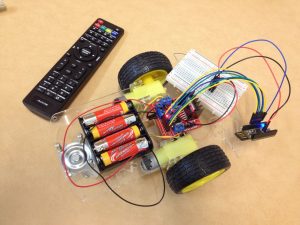
el cheap robot

Here’s my prototype bare-bones robot. There’s nothing really new here, it’s just a couple of motors, a motor controller and an Arduino Nano board. It’s just to show how the most basic robot could be built as a starting point for my students to start thinking about their designs. There’s less than $20 worth of parts (if you buy directly from China, and order in bulk).

In this form it doesn’t do much, but the idea is that students will use the basic design as a platform on which to create their own unique projects. They have to think about what to use for a chassis, how to control it (IR, Bluetooth, WiFi, RF?), to put LEDs on it, sensors and so on.

HomeAssistant + Arduino

OK, HomeAssistant runs on RaspberryPi, but the RPi only has digital in/out, but what if I want to read analog values from sensors? One solution appears to be to use an Arduino, since this is the sort of thing they do well. However, finding details of how to do this seems a bit sketchy. I could use I2C, but that seems a bit tricky. I did read that I can use USB, which is convenient because that will also give me power for the Arduino. To use an Arduino as an add-on board for the RPi, I had read about something called Firmata, which loads as a sketch running on the Arduino. This is easy at the Arduino end, as it is just one of the examples pre-installed, upload and it’s ready to go.

I set up the configuration in HomeAssistant and immediately got a whole heap of errors, mostly referring to needing PyMata 2.14. Now PyMata is a client library that allows Python to control the Arduino. Obviously not part of the standard RPi/Hassbian image. After a bit of messing around here’s what I managed to do:

  1. Plug the Arduino into your computer, load up the IDE and upload the StandardFirmata sketch (found in the Examples submenu)
  2. Plug the Arduino into a USB port on the RPi. Log into the RPi using SSH
  3. At the command line, run:
    sudo pip3 install pymata
  4. If you download the examples from the GitHub repository, you should be able to call the blink sketch to verify that all is working. It should flash the LED 10 times, and you should see the process running in your terminal session counting down. (Note that my UNO clone is connected at ‘/dev/ttyACM0’, so the script works as is.
  5. Add the following entries to your configuration.yaml script and save it:
    arduino:
      port: /dev/ttyACM0
    
    switch:
      platform: arduino
      pins:
        13:
          name: LED
  6. Restart HomeAssistant
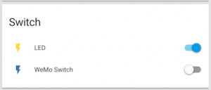
  7. The LED should show up as another switch in your dashboard, and turning it on should light the pin 13 LED on the Arduino

HomeAssistant dashboard with Firmata switch
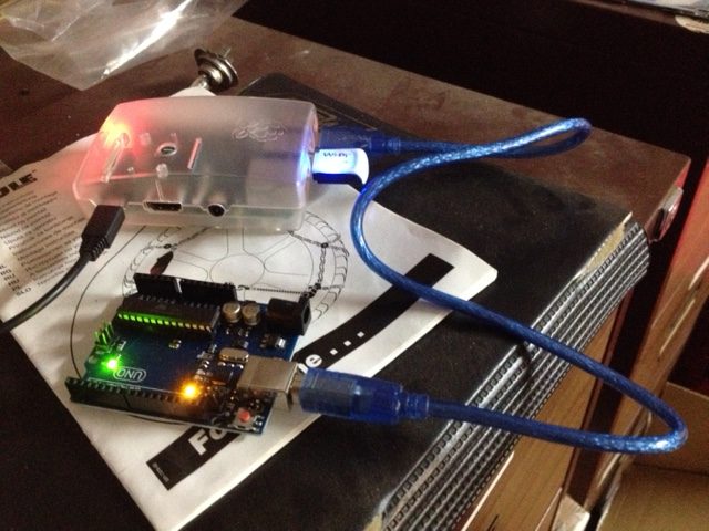
LED on pin 13 of Arduino controlled through HA using Firmata

Note that it appears you can only read analog input pins, and switch digital output pins through this interface. No PWM, and I suppose if you need to read digital inputs then you can do that directly on the RPi.

More info at:


Science Talent Search – Robot Buggy

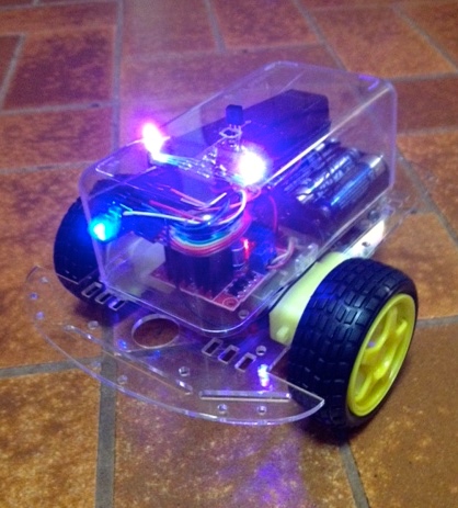
My son entered Science Talent Search with this Arduino-powered buggy. We used IR with a TV remote to issue codes for motor control and combinations of colours for the RGB LEDs.

Programming was fairly simple, but we found issues with power. It seems that motors are very noisy and when they run it can reset the Arduino. We solved this by running the motor off 4 x AA batteries, whilst the Arduino is powered by a phone battery booster. The Arduino in question is actually a Freetronics Leostick, which is a nice small board, and has a USB plug which we just plugged straight into the phone battery.

Arduino + shield

Shield with RF module added

So this project had been sitting on my desk for ages now with the sensors and RF module spread across two breadboards with a mess of wire connecting it all up. Today I finally found some time to add the RF module to a prototyping shield. The other sensors are still on a breadboard and that’s the extra wires hanging off it, but it’s one step closer to a finished project. Some of the soldering was a bit fiddly but worked straight off.

New weather feed online

The new Xively feed is here:
https://personal.xively.com/feeds/1558166025

Data being logged is:

  • indoor temperature
  • indoor humidity
  • outdoor temperature
  • outdoor humidity
  • air pressure
  • total rainfall (since the weather station was set up)
  • light levels (on my study desk, but will be outdoor soon)
  • wind speed, gust speed and direction

The iPhone app simply creates a list of the elements in the datastream, so it is consistent. I also figured out how to display the units in the app.

Putting it all back together

After merging the XC0348 code I had which was receiving the data transmitted by the outdoor sensors with the Xively code there was a bit of tweaking to do to get the sketch to play nicely. The last step was to add the code back for the pressure sensor. This was problematic as the sensor uses I2C and soon as I added the Wire library the whole thing stopped running properly. After some reading I wondered if I was just running out of memory so I commented out a whole lot of serial print statements and it this got things working again. Of course, without the print statements there was a whole lot less debugging going on.

A couple of things that still need attention:

  • the pressure sensor has been timing out often, so I get false values where a negative error code is returned. I’ve increased the timing loop and am seeing if this works better
  • we had a heap of rain overnight and my rainfall figure suddenly dropped because I was only using the LSB, and the count had overflowed. A bit of trial and error and now it is showing the true total. A problem with rainfall is that the sensor reports total rainfall, so this will just keep going up and up. I need some way to keep daily totals. Perhaps I need to add a real time clock?
  • my light values are related to the resistance in the photoresistors, so the curves are inverted i.e. when it is light the value is lowest FIXED Apr 10 – I chose an arbitrary dark value of 1000 and am using that as a reference point to subtract from, so now a bigger value does mean more light rather than more dark!
  • wind direction is returned as an integer between 0 and 31, which seem to correspond to 16 compass points. I think there might be some sort of moving average calculation used by the base station to reduce errors due to rapidly fluctuating wind shifts.

Code time again

Useful links:

These articles together form the source that I drew inspiration from. I didn’t have to do my own signal timing analysis which sounds fascinating but complicated. The above code examples however are written either for Raspberry Pi, or for Arduino using different models of Fine Offset sensors and transmitters.